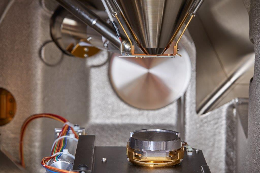
Scanning electron microscopy (SEM) is a powerful technique that can visualize fine surface features on a variety of different materials. These materials can range from metallic parts and polymeric coatings, to inorganic particles and biological specimens. Scanning electron microscopy images samples by raster scanning an electron beam across a sample’s surface, while under vacuum, and recording either secondary electron or back scattered electron emissions. The intensity and position of these emissions allows the microscope’s software to construct an image of the sample surface. Depending on how well the electron beam is focused, features from millimeters to nanometers in size can be resolved. The microscope that Ebatco has is a JSM-6610LV Scanning Electron Microscope, manufactured by JEOL Ltd. The JSM-6610LV can operate in either a high vacuum mode or a low vacuum mode with magnifications up to 300,000 X. In high vacuum mode, the JSM-6610LV can reach a resolution of 3 nm and acceleration voltage of 30 kV for surface topographical analysis. In low vacuum mode, the JSM-6610LV offers variable gas pressures up to 270 Pa within the vacuum chamber to facilitate the analysis of specimens without a conductive coating. This capability is essential for analysis of specimens that are not allowed to be altered by the conductive coating process for compositional and/or forensic reasons, or specimens that are non-conductive or tend to outgas significantly.

Along with the ability to measure lateral features to a high degree of accuracy, SEM can measure the vertical height of features as well through the use of stereoscopic imaging. Similar to the human eye, if one object is viewed by two different sources (both eyes) the images that those two sources collect can be superimposed on top of each other to create a stereoscopic image. This stereoscopic image can be interpreted as a 3D object with a sense of depth. Ebatco’s scanning electron microscope is equipped with image processing software which allow it to analyze and manipulate SEM micrographs in multiple ways including feature height analysis. All that is needed are two SEM images that are viewing the same area on a sample. The key difference between the two images is the degree of sample tilt between the sample surface normal and the electron beam. Typically, one image is taken with a 0° sample tilt and the second image is taken with a 3°-6° tilt. These two images are then superimposed on top of each other in the analysis software and a stereoscopic image is created. From this image, heights of surface features can be measured and recorded. Depending on the software functionalities selected, 1D or 2D surface roughness parameters such as average roughness, root mean square roughness, peak to valley roughness, and more can be measured. The resolution of these height measurements is dependent upon the calibrated pixel size and the degree of sample tilt between images.

For more information on SEM analysis please see our SEM page.

Typical Experimental Results

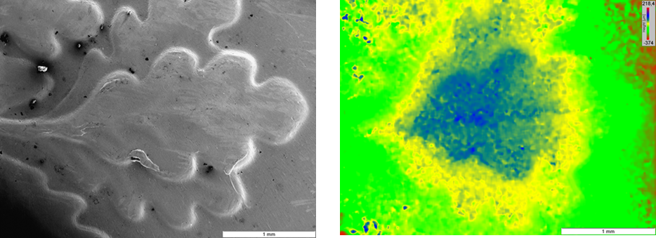
Secondary electron image (left) and height map (right) of an oak leaf on the reverse of a U.S. dime.
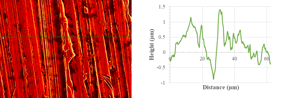
Stacked image of a stainless-steel specimen (left) with a corresponding horizontal line profile (right).
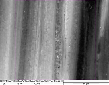
Height map surface roughness measurement of a piece of SS304 weld specimen.
Average Roughness, Sa 0.27 µm
Root Mean Square Roughness, Sq 0.32 µm
Maximum Peak to Valley Roughness, Sz 1.61 µm

Applications

Alloys and MetalsBiofilms Biological Samples Ceramics Chemical Etching
Chemical ImagingCleaning Problems Contamination and Stain Investigation Corrosion Analysis Cross-section Analysis
Failure AnalysisFeature ImagingFeature MeasurementFiber CharacterizationForeign Material Identification
Forensic Analysis Fractography Fracture Characterization Freeze Drying Samples Geochemical Analysis
Geological Samples Glasses Grains and Grain Boundaries High Resolution Imaging IC Failure Analysis
Iron and Steel Material Identification Medical Devices Metallographic Analysis Metallurgy
Micrographs Microstructure Evaluation Nano Materials Nano ParticlesParticle Sizing
Phase Identification Plastic Deformation Plastics and Polymers Scratch and Scuffing Surface Defect Analysis
Thin Films and Coatings Tribological Surfaces Wear Mechanisms Wear Surfaces Welds

For more information please read our application notes.

Instrument: JEOL 6610 LV Scanning Electron Microscope

Key Specifications

FilamentW hairpin filament
ResolutionHigh Vacuum: 3nm (30kV),
8nm (3kV), 15nm (1kV)
Low Vacuum: 4 nm (30kV)
Accelerating Voltage300 V to 30 kV
Magnification5x to 300,000x
LV DetectorMulti-segment BSED
LV Pressure10 to 270 Pa
Sample SizesHeight: 80mm; Width: 178 mm
StageEucentric 5 axis motor control, asynchronous movement, x-y: 125mm-110mm, z: 5mm-8mm, tilt:-10 to 90 degrees, rotation: 360 degrees
Resolution5120 x 3840 pixels
Condenser LensZoom condenser lens
Objective LensConical objective lens