Metallic powders have been consistently used in powder metallurgy (PM), 3D-printing, solder for printed circuit boards, and other industries. The composition and particle size of these powders is critical for their processability and end use application. Uniform particle size facilitates homogenous melting, good interlayer bonding, improved mechanical properties and enhanced surface finish. Ebatco’s NAT Lab has a Beckman Coulter LS 13 320 Laser Diffraction Particle Size Analyzer and a Beckman Coulter Multisizer 4 which can measure particle concentration and size distribution respectively. Our SEM/EDS capabilities also allows us to analyze the microstructure and morphology of metallic powders. Lastly, we can use our STA 449 F3 Jupiter Thermal Analyzer to determine phase transformations that can occur within these metallic powders up to 1650 ºC.

Typical Experimental Results

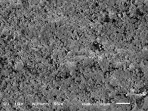
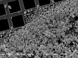
SEM images of a fine gold powder.

Applications

3D Printing Agglomerates Aggregates Alloys Crystal Structures
Element Distribution Failure Analysis Foreign Material Identification Forensic Analysis Fractography
Fracture Study Grains Grain Boundaries Grain Growth Grain Orientation
Grain Size Grain Structure IC Failure Analysis Materials Metals
Metallography Microscopy Microstructure Particle Distribution Particle Size
Phase Diagram Powder Flow Powder Metallurgy Selective Laser Sintering Surface Finish

For more information please read our application notes:

Microporosity Measurement of Zn-Al Casting by Quantitative Image AnalysisPDF

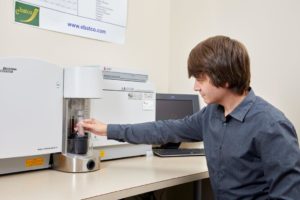
Instruments: Beckman Coulter LS 13 320 Laser Diffraction Particle Size Analyzer with ULM and Sonication Control Unit connected

Key Specifications:

Filament W hairpin filament
Resolution High Vacuum: 3nm (30kV),
8nm (3kV), 15nm (1kV)
Low Vacuum: 4 nm (30kV)
Accelerating Voltage 300 V to 30 kV
Magnification 5x to 300,000x
LV Detector Multi-segment BSED
LV Pressure 10 to 270 Pa
Sample Sizes Height: 80mm; Width: 178 mm
Stage Eucentric 5 axis motor control, asynchronous movement, x-y: 125mm-110mm, z: 5mm-8mm, tilt:-10 to 90 degrees, rotation: 360 degrees
Resolution 5120 x 3840 pixels
Condenser Lens Zoom condenser lens
Objective Lens Conical objective lens
Microporosity Measurement of Zn-Al Casting by Quantitative Image Analysis


With the development of computer technology, quantitative software image analysis has become feasible. Computer software can count grain and particle size, identify nonmetallic inclusions, and calculate porosity more efficiently than traditional manual methods. In this app note, the micro porosity of a Zn-Al casting is measured to demonstrate how the quantitative image analysis works.


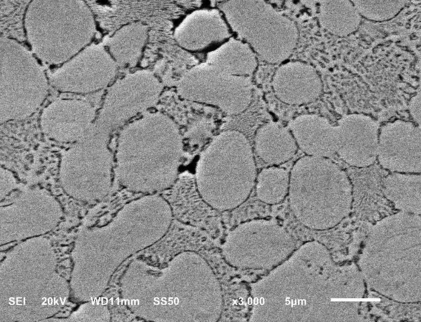
Figure 1. Typical microstructure of the Zn-Al alloy

Figure 1 shows the typical microstructure of a Zn-Al alloy. The alloy is composed of a lamellar eutectic α phase (dendrite network) and a zinc-rich η phase. In cast zinc, Al can refine the grain size and form a fine equiaxed grain structure. This can improve the strength, ductility, and toughness of zinc castings. Tiny holes form between the arms of the dendritic network due to gas evolution during the solidification process. In this sample, the relatively large pores are shrinkage cavities, which are more or less fissured and cave like in shape. It is impossible to completely remove shrinkage cavities in Zn-Al castings.

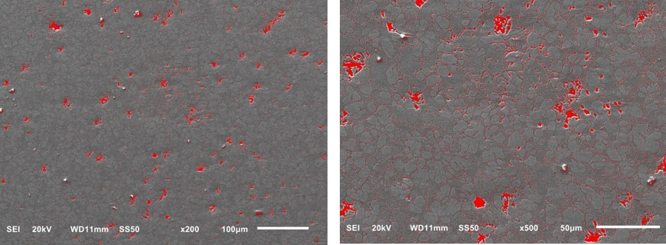
In this work, pores larger than 5 µm were selected for porosity measurement. Based upon practical applications or customer requirements, different pore sizes can be selected to calculate the porosity of the casting. To determine the effects of image magnification on porosity measurement, 200X and 500X micrographs are compared. For each magnification, five random areas were selected to measure the porosity of the casting. Figure 2 shows a typical distribution of pores within the Zn-Al casting.

Figure 2. Typical porosity measurement results using 200X (left) and 500X (right) magnification. (Pore sizes less than 5 µm were excluded from statistical calculations.)

Table 1 lists the porosity measurements with 200X and 500X magnifications. Based upon the results of the image analysis software, the average pore areas measured at 200X and 500X magnifications were very similar, around 19.74 µm2. The porosities (or percentage of the total image area occupied by pores) were consistent when measured at 200X and 500X magnification.

Table 1. Porosity measurement results with different magnifications

200X Magnification 500X Magnification
area Average size (µm2) Percent area (%) Average size (µm2) Percent area (%)
area 1 19.80 0.98 17.91 1.38
area 2 18.76 1.13 21.42 1.36
area 3 23.95 1.37 24.72 0.97
area 4 18.78 0.92 20.65 1.15
area 5 17.51 0.75 13.93 0.86
average 19.76 1.03 19.72 1.15
ASTM Number Title Website Link
A892 – 06 Standard Guide for Defining and Rating the Microstructure of High Carbon Bearing Steels Link
B276 – 05(2015) Standard Test Method for Apparent Porosity in Cemented Carbides Link
B487 – 85(2013) Standard Test Method for Measurement of Metal and Oxide Coating Thickness by Microscopical Examination of Cross Section Link
B578 – 87(2015) Standard Test Method for Microhardness of Electroplated Coatings Link
B657 – 05 Guide for Metallographic Identification of Microstructure in Cemented Carbides Link
B748 – 90(2016) Standard Test Method for Measurement of Thickness of Metallic Coatings by Measurement of Cross Section with a Scanning Electron Microscope Link
B796 – 02 Standard Test Method for Nonmetallic Inclusion Content of Powders Intended for Powder Forging (P/F) Applications Link
E1508 – 98(2008) Standard Guide for Quantitative Analysis by Energy-Dispersive Spectroscopy Link
E2651 – 10 Standard Guide for Powder Particle Size Analysis Link
E3 – 01(2007)e1 Standard Guide for Preparation of Metallographic Specimens Link
E384 – 09 Standard Test Method for Microindentation Hardness of Materials Link
E384 – 10e2 Standard Test Method for Knoop and Vickers Hardness of Materials Link
E407 – 07(2015)e1 Standard Practice for Microetching Metals and Alloys Link
E45 – 05e3 Standard Test Methods for Determining the Inclusion Content of Steel Link
E562 – 11 Standard Test Method for Determining Volume Fraction by Systematic Manual Point Count Link
E768 – 99(2010)e1 Standard Guide for Preparing and Evaluating Specimens for Automatic Inclusion Assessment of Steel Link
E930 – 99(2015) Standard Test Methods for Estimating the Largest Grain Observed in a Metallographic Section (ALA Grain Size) Link
ISO Number Title Link
9220:1988 Metallic coatings — Measurement of coating thickness — Scanning electron microscope method Link
643:2012 Steels — Micrographic determination of the apparent grain size Link
5949:1983 Tool steels and bearing steels — Micrographic method for assessing the distribution of carbides using reference photomicrographs Link
4499-4:2016 Hardmetals — Metallographic determination of microstructure — Part 4: Characterisation of porosity, carbon defects and eta-phase content Link
4499-1:2008 Hardmetals — Metallographic determination of microstructure — Part 1: Photomicrographs and description Link
18203:2016 Steel — Determination of the thickness of surface-hardened layers Link